New FP-ELS-L sensor (installation, technical information) | News
New FP-ELS-L sensor (installation, technical information)
15.03.2021. New FP-ELS-L sensor (installation, technical information)
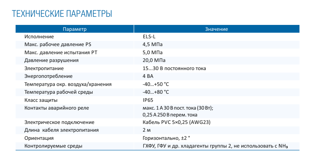
The Russian plant of refrigeration equipment components Frigopoint announces the launch of serial production of new FP-ELS-L level sensors. New sensors measurement technology based on the Hall sensor, similar to that used in FP-ELS2 level sensors and FP-ERL4 oil level regulators. The FP-ELS-L level sensor is intended for use as an electronic meter for limit values of the levels of working media in capacitive equipment - vessels and apparatus working under pressure. To be installed to the connection ports of visual level control devices (interfaces). The sensors are compatible with all HFC, CFC and HCFC refrigerants, mineral and synthetic oils. The degree of protection of the shell is IP65.
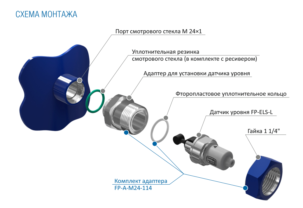
The sensors are mounted on the sight glass port of the receiver. To mount them, use the FP-A-M24-114L adapter:
Installation instructions below:
Install the adapter (supplied separately, includes rubber / PTFE seals and flare nut) in the sight glass port. The maximum tightening torque of the adapter is 30 Nm.
Install the sensor into the adapter port. Orientation of the sensor for low level control - arrow up. The orientation of the sensor for top level control is with an arrow pointing down.
Fasten the level sensor with the union nut, holding the sensor by the flats on the metal part of the sensor. The maximum tightening torque of the union nut is 110 Nm. Place the sensor case horizontally along the flats. The maximum possible deviation is ± 2 °.
If the port does not match the sensor, use an adapter that is supplied separately.
Protect the output relay contacts with a circuit breaker or fuse rated at 1A for DC and 0.25A for AC, otherwise there is a high risk of burnout of the output relay contact circuit.
It is not recommended to use power contactors as a load. Be sure to check the starting power consumption of the coil and compare the maximum power of the relay output contacts to the sensors. If there is no starting power consumption in the technical specifications for the contactor to be connected, its value should be taken as a 12-point holding power consumption. When connecting power contactors, we recommend using intermediate relays.
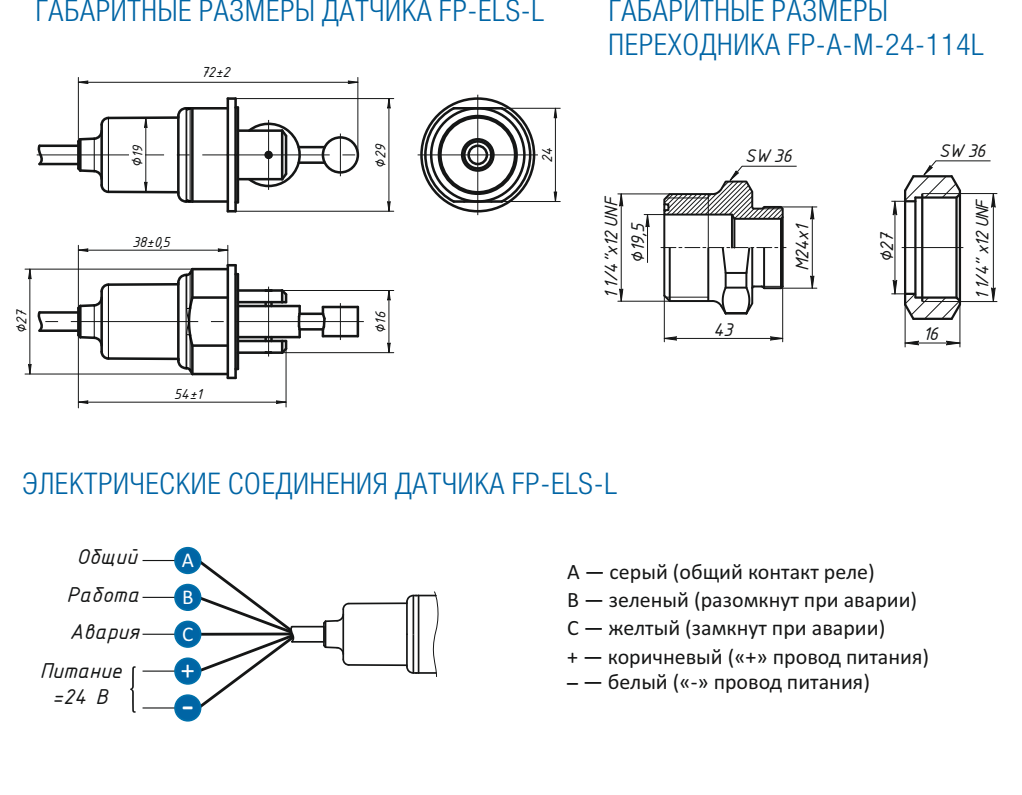
Make electrical connections in accordance with fig.
Observe the polarity of the power supply wires. Incorrect connection will lead to imminent sensor failure.
During operation, it is recommended to keep the sensor connected to the power supply at all times, even if the system is in standby mode.
During service work related to the removal of the sensor and adapter, when they are reinstalled, all O-rings must be replaced with new ones, using a repair set of seals. The seal repair kit is not included with the transmitter and is supplied separately.
Russian instruction link >>>>
English instruction link>>>>
Russian leaflet link>>>>
The Russian plant of refrigeration equipment components Frigopoint announces the launch of serial production of new FP-ELS-L level sensors. New sensors measurement technology based on the Hall sensor, similar to that used in FP-ELS2 level sensors and FP-ERL4 oil level regulators. The FP-ELS-L level sensor is intended for use as an electronic meter for limit values of the levels of working media in capacitive equipment - vessels and apparatus working under pressure. To be installed to the connection ports of visual level control devices (interfaces). The sensors are compatible with all HFC, CFC and HCFC refrigerants, mineral and synthetic oils. The degree of protection of the shell is IP65.
The sensors are mounted on the sight glass port of the receiver. To mount them, use the FP-A-M24-114L adapter:
Installation instructions below:
Install the adapter (supplied separately, includes rubber / PTFE seals and flare nut) in the sight glass port. The maximum tightening torque of the adapter is 30 Nm.
Install the sensor into the adapter port. Orientation of the sensor for low level control - arrow up. The orientation of the sensor for top level control is with an arrow pointing down.
Fasten the level sensor with the union nut, holding the sensor by the flats on the metal part of the sensor. The maximum tightening torque of the union nut is 110 Nm. Place the sensor case horizontally along the flats. The maximum possible deviation is ± 2 °.
If the port does not match the sensor, use an adapter that is supplied separately.
Protect the output relay contacts with a circuit breaker or fuse rated at 1A for DC and 0.25A for AC, otherwise there is a high risk of burnout of the output relay contact circuit.
It is not recommended to use power contactors as a load. Be sure to check the starting power consumption of the coil and compare the maximum power of the relay output contacts to the sensors. If there is no starting power consumption in the technical specifications for the contactor to be connected, its value should be taken as a 12-point holding power consumption. When connecting power contactors, we recommend using intermediate relays.
Make electrical connections in accordance with fig.
Observe the polarity of the power supply wires. Incorrect connection will lead to imminent sensor failure.
During operation, it is recommended to keep the sensor connected to the power supply at all times, even if the system is in standby mode.
During service work related to the removal of the sensor and adapter, when they are reinstalled, all O-rings must be replaced with new ones, using a repair set of seals. The seal repair kit is not included with the transmitter and is supplied separately.
Russian instruction link >>>>
English instruction link>>>>
Russian leaflet link>>>>